


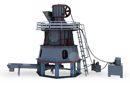
MTW European Type Trapezium Mill
Input size:30-50mm
Capacity: 3-50t/h
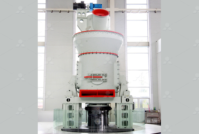
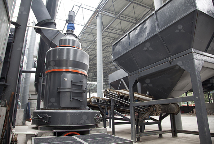
LM Vertical Roller Mill
Input size:38-65mm
Capacity: 13-70t/h
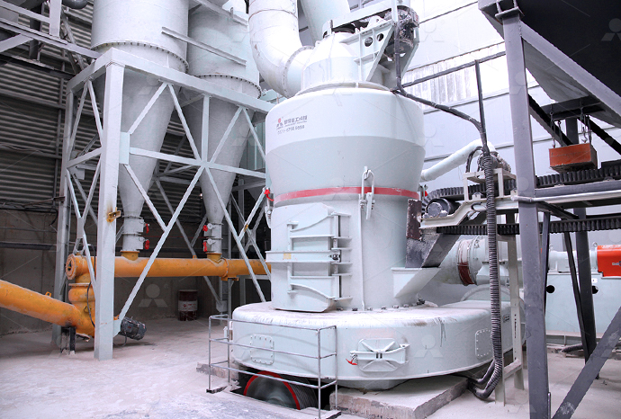
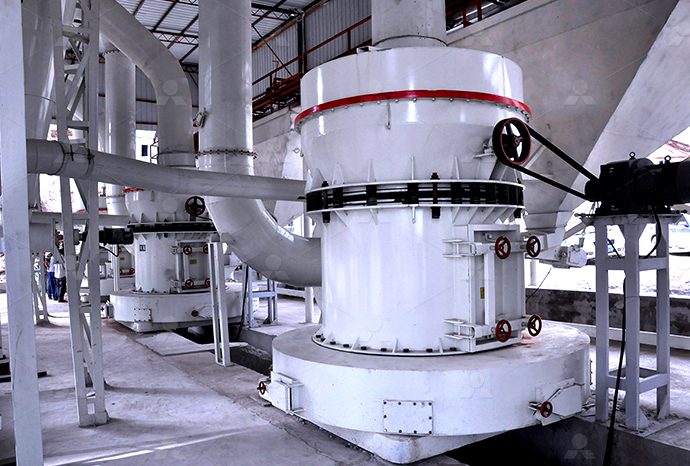
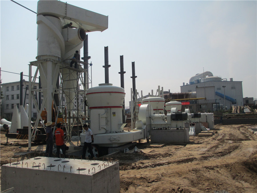
Raymond Mill
Input size:20-30mm
Capacity: 0.8-9.5t/h
Sand powder vertical mill
Input size:30-55mm
Capacity: 30-900t/h
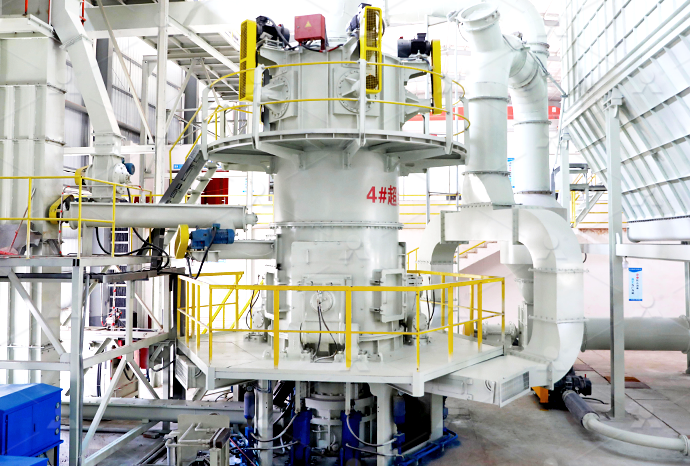
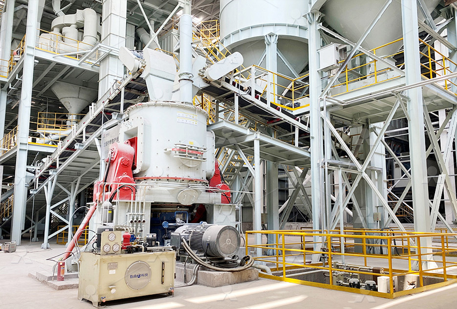
LUM series superfine vertical roller grinding mill
Input size:10-20mm
Capacity: 5-18t/h
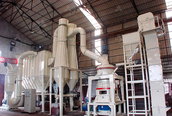
MW Micro Powder Mill
Input size:≤20mm
Capacity: 0.5-12t/h

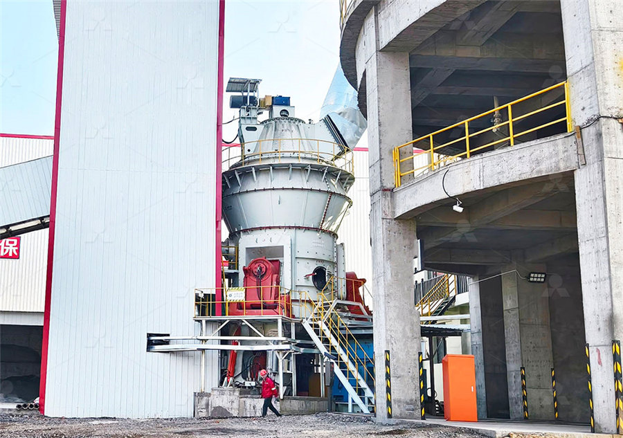
LM Vertical Slag Mill
Input size:38-65mm
Capacity: 7-100t/h
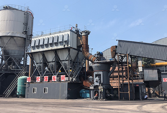
LM Vertical Coal Mill
Input size:≤50mm
Capacity: 5-100t/h
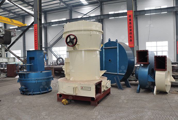
TGM Trapezium Mill
Input size:25-40mm
Capacity: 3-36t/h
MB5X Pendulum Roller Grinding Mill
Input size:25-55mm
Capacity: 4-100t/h
Straight-Through Centrifugal Mill
Input size:30-40mm
Capacity: 15-45t/h
Barite grinding machine control schematic diagram

INSTRUCTION MANUAL FOR PRECISION SURFACE GRINDER
(1)The machine must not be installed in areas with explosive powders or materials (2)Combustible liquids must not be used as a cuting fluid (3)The machine should not be Figure 2 shows the schematic diagram of the grinding machine and instrumentation used The tests were carried out for 15 different grinding conditions, using 5µm as the lowest depth ofSchematic diagram of the grinding machine and instrumentationLocation of the machine will influence the grinding precision and effeciency You have to carefully dispose it as well as boring machine Very precise process is asked by any kind of grinding USA J 1 MAIN PARTS OF THE MACHINE Kent Kent Industrial USAThe grinding experiment results using the optimal grinding parameters agree well with the designated geometrical parameters of twist drill and show a marked improvement in grindingSchematic diagram of the grinder Download Scientific Diagram

Schematic of control organization of surface grinding machine [7
Download scientific diagram Schematic of control organization of surface grinding machine [7] from publication: CONTROL OF VERTICAL SPINDLE SURFACE GRINDING FROM A MULTI A grinding machine is a material removal machine having geometrically nondefined, bonded cutting edges and rotational or linear relative movement between tool and workpiece The Different Types of Grinding Machine IJRPRCylindrical Grinding Machines As a global leader in grinding machine technology, Toyoda offers an extensive lineup of highperformance universal, cylindrical, camshaft, and crankshaft grinding machines Originally designed for high Parts and Functions of Grinding MachineSection 7: Best Practices for CNC Machine Schematic Diagrams Techniques for organizing and labeling schematic diagrams Importance of documentation and keeping schematic diagrams up to date Section 8: Future Developments in CNC Machine Schematic Diagrams Overview of emerging technologies and advancements in schematic diagrams for CNC machinesThe Ultimate Guide to Understanding CNC Machine Schematic Diagrams

Grinding Machine: Definition, Parts, Working
2021年5月5日 The grinding machine is widely used to finish the workpiece Do you know why? Because the work removal rate is low between 025 to 05 mm (This can be advantages or disadvantages also for various types of works) Download scientific diagram (a) Schematic diagram of rail grinding machine, (b) contact mode of grinding test 1Inverter motor; 2Rail specimen; 3Grinding wheel; 4Wheel fixture; 5Slider; 6 (a) Schematic diagram of rail grinding machine, (b) contact Diagrams include sequence diagrams, flow charts, entity relationship diagrams, cloud architecture diagrams, data flow diagrams, network diagrams, and more Brought to you by the folks at Want this for your team? Let's chat if your team has a specific diagramming workflow to automateDiagramGPT – AI diagram generatorDownload scientific diagram Schematic diagram for the control of cylindrical grinding process using FLC from publication: Design of an Adaptive Controller for Cylindrical Plunge Grinding Process Schematic diagram for the control of cylindrical grinding
Schematic diagram of robotic belt grinding ResearchGate
Download scientific diagram Schematic diagram of robotic belt grinding from publication: Application of novel force control strategies to enhance robotic abrasive belt grinding quality of aero Download scientific diagram Schematic diagram of grinding chamber of hammer mill from publication: Grinding of Coriander Seeds: Modeling of Particle Size Distribution and Energy Studies Schematic diagram of grinding chamber of hammer millThe milling machine schematic diagram typically includes symbols and labels to represent different parts, such as motors, switches, sensors, relays, and control units These symbols and labels enable users to quickly identify specific components and understand their functions in the milling machine systemHow to Interpret and Use a Milling Machine Schematic Diagram2020年11月8日 Figure 4 is a schematic diagram of a ball mill/cyclone control system Laboratory Flotation Machines; Comminution Testing Laboratory Crushers; Jar Bottle Rollers; The primary objectives for the grinding control system can be stated as to provide with a flexible and adaptable easy to use system to either:Grinding Circuit Control Strategy 911Metallurgist
Schematic Diagram Maker Free Online App
Product Management Roadmap features, brainstorm, and report on development, so your team can ship features that users love Software Engineering Design and maintain complex systems collaboratively Information Technology Visualize Schematic Diagram of Lathe Machine A lathe machine is a versatile machine tool used in metalworking operations It is used to shape various workpieces by rotating them against a cutting tool A schematic diagram of a lathe machine Understanding the Inner Workings of a Lathe Machine: The idea of schematic diagrams came into existence somewhere in 1300 AD when the firstever geographical map, which is now known as Atlas, was drawn Later, the same concept was used to draw the maps of stars and Schematic Diagram A Complete Tutorial with Free Download scientific diagram Schematic diagram of rail grinding machine and the friction pair of rail grinding aSiemens inverter motor bFoundation bed cMachine rail dTiming belt drive e Schematic diagram of rail grinding machine and the friction pair

Microgrinding machining scheme and photo of mold core: (a) Schematic
Figure 1 shows the microgrinding machining scheme and photo of Ti 3 SiC 2 mold core surface with Vgrooved array structures through a computer numerical control (CNC) precision grinding machineDownload scientific diagram Rail grinding friction machine: (a) schematic diagram; (b) the position of acceleration sensor; (c) grinding specimens from publication: Influence of granularity of Rail grinding friction machine: (a) schematic diagram; (b) the 2018年9月8日 If you’re an electrical engineer, mechanic, technician, or DIY enthusiast, chances are you’ve encountered schematic diagrams in your work These diagrams provide a ‘map’ of the relationship between circuits, components, and devices within an electronic system, making them essential to engineers and technicians trying to diagnose and troubleshoot problemsHow To Read And Interpret Schematic DiagramsDownload scientific diagram Schematic diagram of a grinding passage from publication: Hounsfield Mechanical testing machine used in compression test [20] Schematic diagram of a grinding passage ResearchGate
Schematic diagram of the grinding system ResearchGate
Turbine blades are mostly machined by grinding [3], which enables manufacturers to meet high precision and surface roughness requirements [4] Another, and the most expensive way to machine heat Schematic diagram of rail grinding machine 1Rolling bearing; 2proximity switch; 3coupling arrangement; 4clutch; 5rolling bearing; 6motion fixture; 7grinding stone; 8rail specimens; 9static Schematic diagram of rail grinding machine 1Rolling bearing Download scientific diagram A schematic of a closedloop cement grinding control system Adapted from [6] from publication: Coarse Return Prediction in a Cement Industry’s Closed Grinding A schematic of a closedloop cement grinding 2019年7月22日 Comment: The schematic diagram should NOT show the physical/mechanical representation of a connector, this is the realm of the associated assembly drawing After all you don’t show on a schematic Understanding Schematics Technical Articles All
Schematic diagram of the grinder Download
Download scientific diagram Schematic diagram of the grinder from publication: Analysis and simulation for a parallel drill point grinder:Part I: Kinematics, workspace and singularity analysis 2024年6月28日 Introduction In the world of electronics and engineering, the ability to read and interpret schematics is a fundamental skill But what exactly are schematics, and why are they so important? Schematics, or circuit diagrams, are visual representations of electronic circuitsThey use symbols to represent different electronic components and show how these components The Basics of Schematics: Understanding Circuit Diagrams and2023年10月6日 Cylindrical Grinding Machine: Know Diagram, Parts, Working, Types and Applications Last Updated on Oct 6, 2023 Mounted on the cross slide, the wheel head facilitates vertical movement to control the depth of the cut This can be adjusted either manually via the crossfeed handwheel or through a power sourceCylindrical Grinding MachineDiagram, Parts, Working, Types, UsesDownload scientific diagram Schematic diagram of milling machine from publication: Tool wear prediction in face milling of stainless steel using singular generative adversarial network and LSTM Schematic diagram of milling machine Download Scientific Diagram
.jpg)
Grinding in Ball Mills: Modeling and Process Control
2012年6月1日 PDF The paper presents an overview of the current methodology and practice in modeling and control of the grinding process in industrial ball mills The schematic diagram of a twoinput 2021年3月8日 An electrical schematic is a diagram that shows how all of the wires and components in an electronic circuit are connected They’re like a map for building or troubleshooting circuits, and can tell you almost everything you How to Read Electrical Schematics Circuit BasicsDouble side grinding is a process with high processing efficiency in which the wheel and the workpiece are in surface contact But the phenomenon that the workpiece surface profile is out of The schematic diagram of double side grindingIn conclusion, a grinder parts diagram is a helpful tool for understanding the various components of a grinder and how they work together to create a grinding machine It helps users identify and locate specific parts, making maintenance and repair tasks easier and more efficientThe Ultimate Guide to Understanding Grinder Parts Diagram

Parts and Functions of Grinding Machine
Cylindrical Grinding Machines As a global leader in grinding machine technology, Toyoda offers an extensive lineup of highperformance universal, cylindrical, camshaft, and crankshaft grinding machines Originally designed for high Section 7: Best Practices for CNC Machine Schematic Diagrams Techniques for organizing and labeling schematic diagrams Importance of documentation and keeping schematic diagrams up to date Section 8: Future Developments in CNC Machine Schematic Diagrams Overview of emerging technologies and advancements in schematic diagrams for CNC machinesThe Ultimate Guide to Understanding CNC Machine Schematic Diagrams2021年5月5日 The grinding machine is widely used to finish the workpiece Do you know why? Because the work removal rate is low between 025 to 05 mm (This can be advantages or disadvantages also for various types of works) Grinding Machine: Definition, Parts, Working Download scientific diagram (a) Schematic diagram of rail grinding machine, (b) contact mode of grinding test 1Inverter motor; 2Rail specimen; 3Grinding wheel; 4Wheel fixture; 5Slider; 6 (a) Schematic diagram of rail grinding machine, (b) contact
.jpg)
DiagramGPT – AI diagram generator
Diagrams include sequence diagrams, flow charts, entity relationship diagrams, cloud architecture diagrams, data flow diagrams, network diagrams, and more Brought to you by the folks at Want this for your team? Let's chat if your team has a specific diagramming workflow to automateDownload scientific diagram Schematic diagram for the control of cylindrical grinding process using FLC from publication: Design of an Adaptive Controller for Cylindrical Plunge Grinding Process Schematic diagram for the control of cylindrical grinding Download scientific diagram Schematic diagram of robotic belt grinding from publication: Application of novel force control strategies to enhance robotic abrasive belt grinding quality of aero Schematic diagram of robotic belt grinding ResearchGateDownload scientific diagram Schematic diagram of grinding chamber of hammer mill from publication: Grinding of Coriander Seeds: Modeling of Particle Size Distribution and Energy Studies Schematic diagram of grinding chamber of hammer mill
43.jpg)
How to Interpret and Use a Milling Machine Schematic Diagram
The milling machine schematic diagram typically includes symbols and labels to represent different parts, such as motors, switches, sensors, relays, and control units These symbols and labels enable users to quickly identify specific components and understand their functions in the milling machine system2020年11月8日 Figure 4 is a schematic diagram of a ball mill/cyclone control system Laboratory Flotation Machines; Comminution Testing Laboratory Crushers; Jar Bottle Rollers; The primary objectives for the grinding control system can be stated as to provide with a flexible and adaptable easy to use system to either:Grinding Circuit Control Strategy 911Metallurgist